Make power part of your system's control, test and maintenance workflow.
On models with the required digital features, operating data, approved settings and fault information can help you bring up equipment, repeat configurations and diagnose problems. Start with your input, load and cooling requirements, then confirm the selected module's interface and functions.
Selection and supply inquiries. Availability, lead time and supporting documentation are confirmed for the selected model.
Specifications below are selection summaries. Product files are not hosted for download, and this website does not accept file uploads. For the current datasheet/spec, drawings or detailed operating conditions, email market@jingmusecurity.com.
Digital power advantages, from bring-up to maintenance
Turn supported monitoring and configuration into a repeatable engineering workflow. Confirm each function, host interface and command set for the selected module before design-in.
Bring-up with evidence
Relate supported voltage, current and temperature readings to equipment load and test events.
Use documented settings to evaluate power behavior within the module's permitted limits.
Verify available telemetry, accuracy, update rate and measurement conditions in the selected model's documentation.
Repeat approved configuration
For configurable models, define an approved set of output, protection or soft-start parameters.
Plan write-and-readback checks so equipment variants and production batches use the intended settings.
Confirm allowed adjustment ranges, start-up defaults, write protection and whether settings persist after power cycling.
Diagnose in context
Bring supported operating status and fault information into host records to investigate equipment events.
Define who records data, how an approved configuration is restored and what happens if communication is lost.
Confirm fault flags or history, retention, interface levels, commands and host compatibility. PMBus / I²C and remote access are model-specific, not assumed.
Digital management does not by itself establish higher efficiency, lower ripple, faster transient response or lower cost. Compare the selected models under the same input, load and thermal conditions, and review isolation, protection and derating requirements separately.
Digital DC-DC selection: 66 series, six families
1/16, 1/8 and 1/4 brick formats cover different nominal output ratings from 80 W to 420 W across the catalog. The 28 V and 48 V labels describe nominal input buses, not the actual operating range. Use the row for the selected series below.
1/8 brick · 28 V bus
12 series · 125–240 W
2.5–48 V nominal output options
Discrete model options, not a continuously adjustable range or every voltage/power combination.
1/8 brick · 28 V nominal input bus · 12 series — expand table
Select a series to view its full specification tables. x denotes a placeholder, not a complete order code. Each row has independent ratings. On small screens, scroll this table horizontally.
1/8 brick · 48 V nominal input bus · 10 series — expand table
Select a series to view its full specification tables. x denotes a placeholder, not a complete order code. Each row has independent ratings. On small screens, scroll this table horizontally.
1/16 brick · 28 V nominal input bus · 13 series — expand table
Select a series to view its full specification tables. x denotes a placeholder, not a complete order code. Each row has independent ratings. On small screens, scroll this table horizontally.
1/16 brick · 48 V nominal input bus · 8 series — expand table
Select a series to view its full specification tables. x denotes a placeholder, not a complete order code. Each row has independent ratings. On small screens, scroll this table horizontally.
1/4 brick · 28 V nominal input bus · 12 series — expand table
Select a series to view its full specification tables. x denotes a placeholder, not a complete order code. Each row has independent ratings. On small screens, scroll this table horizontally.
1/4 brick · 48 V nominal input bus · 11 series — expand table
Select a series to view its full specification tables. x denotes a placeholder, not a complete order code. Each row has independent ratings. On small screens, scroll this table horizontally.
Digital power features and typical performance curves
Extracted from supplied 2025V2 specification documents, reviewed on 2026-10-29. These are typical characteristics from those documents, not independent Jingmu measurements or guaranteed limits. Original plots without company identifiers are reproduced without redrawing data, axes or legends; documented conditions appear alongside each plot.
2828x-240x function example: specification pages 1 and 3–5
Digital function
Documented capability for this series
Integration value and confirmation
Operating telemetry
Input voltage, output voltage, output current and temperature readings.
Relate operating status to equipment load and test records; confirm accuracy and update rate.
Runtime parameter settings
Output voltage, overcurrent threshold, overtemperature threshold and soft-start rise time.
Define approved settings for a power rail; confirm allowed ranges and protection behavior.
PMBus digital interface
Clock/data interface for parameter reading and writing; the documentation describes digital PID/PWM control separately.
Plan host communication and readback checks; obtain the actual command set and electrical levels.
Ready and fault signals
PGOOD output-ready indication and a fault-alert signal, in addition to the digital interface.
Coordinate equipment startup and fault handling; check signal levels, timing and recovery.
Input-side / output-side enable
Separate RC and EN controls; output-side control requires input-side enable to be on.
Choose the correct positive/negative-logic order code and check the model-specific pinout.
Saved configuration
The supplied application section states that configured parameters are retained.
Plan power-cycle/readback acceptance checks; confirm firmware, defaults and programming-tool scope.
This function table is a documented 2828x-240x example, not a claim for all 66 series. Software, USB programmers and remote-management platforms are not listed as standard inclusions; confirm the actual scope by email.
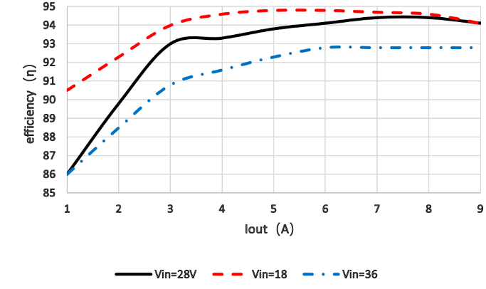
2828x-240x · 28 V / 240 W
1/8 brick · Rated input 18–36 V · Nominal output 28 V / 240 W
x is a series placeholder, not a complete order code. Plotted current ranges do not increase the nominal power rating or establish continuous full power across the full input/temperature range.
Conversion efficiency
2828x-240x · 2025V2 · p3 typical characteristics
Horizontal axis: output current 1–9 A; vertical axis: efficiency. Input-voltage traces: Vin = 18 / 28 / 36 V. Temperature and cooling conditions are not stated.
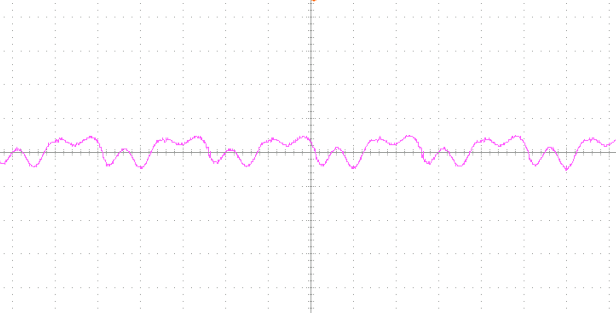
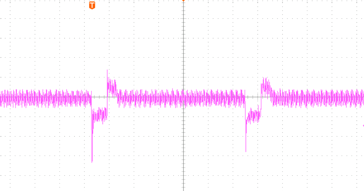
Output ripple waveform
2828x-240x · 2025V2 · p3 typical characteristics
Cin = 220 µF; Cout = 440 µF; voltage scale 100 mV/div; time scale 1 µs/div. Input voltage, load current, temperature, cooling, measurement bandwidth and probe method are not stated.
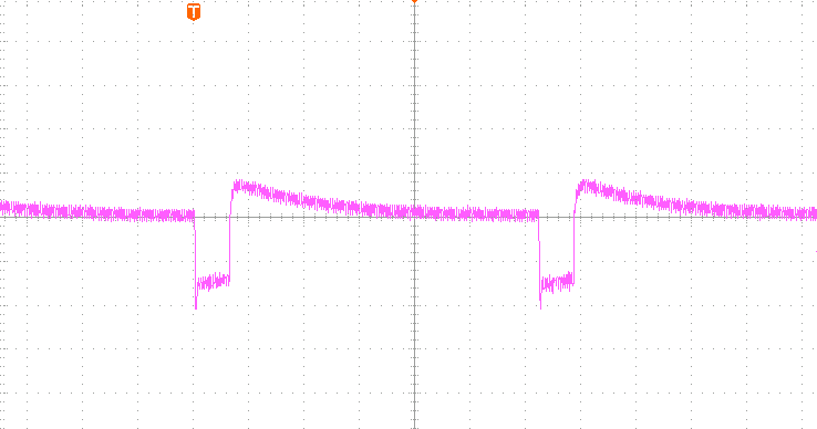
Load-transient response
2828x-240x · 2025V2 · p3 typical characteristics
Cout = 440 µF; load steps 0 → 9 → 0 → 9 → 0 A; voltage scale 500 mV/div; time scale 4 ms/div. Input voltage, temperature, cooling, load slew rate and measurement bandwidth are not stated.
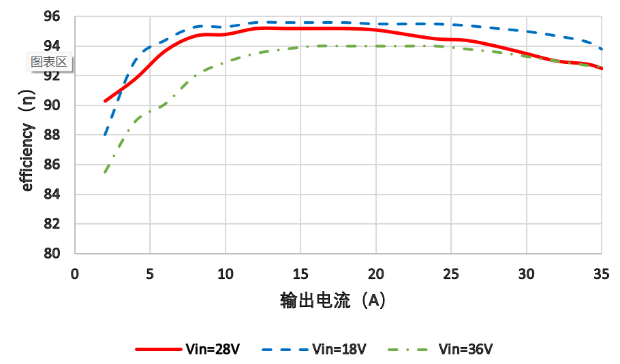
2812x-420x · 12 V / 420 W
1/4 brick · Rated input 18–36 V · Nominal output 12 V / 420 W
x is a series placeholder, not a complete order code. Plotted current ranges do not increase the nominal power rating or establish continuous full power across the full input/temperature range.
Conversion efficiency
2812x-420x · 2025V2 · p3 typical characteristics
Horizontal axis: output current 0–35 A; vertical axis: efficiency. Input-voltage traces: Vin = 18 / 28 / 36 V. Temperature and cooling conditions are not stated.
Load-transient response
2812x-420x · 2025V2 · p3 typical characteristics
Cout = 440 µF; load steps 0 → 35 → 0 → 35 → 0 A; voltage scale 500 mV/div; time scale 4 ms/div. Input voltage, temperature, cooling, load slew rate and measurement bandwidth are not stated.
2828x-120x · 28 V / 120 W
1/16 brick · Rated input 18–36 V · Nominal output 28 V / 120 W
x is a series placeholder, not a complete order code. Plotted current ranges do not increase the nominal power rating or establish continuous full power across the full input/temperature range.
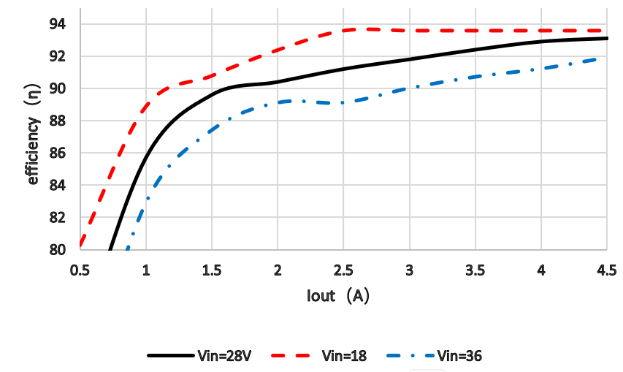
Conversion efficiency
2828x-120x · 2025V2 · p3 typical characteristics
Horizontal axis: output current 0.5–4.5 A; vertical axis: efficiency. Input-voltage traces: Vin = 18 / 28 / 36 V. Temperature and cooling conditions are not stated.
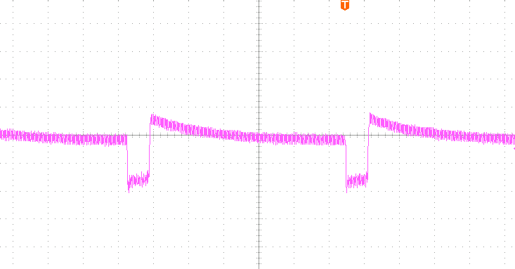
Load-transient response
2828x-120x · 2025V2 · p3 typical characteristics
Cout = 220 µF; load steps 0 → 4.5 → 0 → 4.5 → 0 A; voltage scale 500 mV/div; time scale 4 ms/div. Input voltage, temperature, cooling, load slew rate and measurement bandwidth are not stated.
Digital vs analog: compare system value, not labels
Our power catalog is digital only. Analog approaches below are engineering comparisons, not an additional product line. Confirm digital management functions for each model.
System-level architecture comparison, not measured model results
Decision
With digital management (model-specific)
Analog approach and comparison boundary
Visibility
Bring supported telemetry and fault information into the host to aid troubleshooting.
External sensing and management can add similar functions; compare accuracy, update rate and integration effort.
Configuration
Set supported output, startup or protection parameters within documented limits and read them back.
Hardware settings or external control are alternatives; compare ranges, defaults, persistence and write protection.
System coordination
Use the actual protocol, command set and alarm behavior for host supervision.
A digital interface does not establish a digital control loop. Validate faults and recovery in either architecture.
Electrical performance and cost
Evaluate the selected model under comparable conditions, not the digital label.
Match input, load, temperature, cooling and measurement bandwidth before comparing efficiency, ripple, transients and total cost.
Where digital management earns its place
Start with the equipment task, then connect power selection to control, test and maintenance. These are requirement scenarios, not delivered case studies; confirm each function for the selected model rather than all 66 series.
RF amplifiers and communications equipment
Customer task: Bring up multiple power rails and assess burst-load behavior in the complete equipment.
Digital-management value: Supported sequencing, enable and fault information can help the host coordinate startup and relate abnormal events.
Acceptance focus: Confirm actual signals and commands. Validate load steps under matched input, load and thermal conditions; digital features do not establish performance.
Customer task: Link power configuration and operating state to test records when reviewing differences.
Digital-management value: Supported configuration readback and telemetry can add context to repeatability checks and troubleshooting.
Acceptance focus: Confirm time correlation, readings and interfaces. A digital module is not a programmable laboratory supply; automated test software is a separate scope to confirm.
Customer task: Investigate intermittent power problems before planning an on-site maintenance visit.
Digital-management value: Supported status, telemetry and fault context can inform remote diagnosis.
Acceptance focus: Confirm log retention, who records it and communication-loss behavior. Monitoring alone does not establish predictive maintenance or remaining life.
The selection tables cover 66 series references in six groups: 1/16, 1/8 and 1/4 brick modules for nominal 28 V or 48 V input buses. Listed nominal power ratings span 80–420 W across different models. Each row defines its own input range, output voltage and power; these are not interchangeable combinations or stock confirmations.
What is the advantage of digital power?
The practical benefits are better visibility during bring-up, repeatable approved settings and more context for fault diagnosis. Models with the relevant functions can expose operating data and allow documented configuration through host control. Confirm readable values, commands, limits, persistence, tools and host integration for the selected model; these functions are not guaranteed across every series.
When is an upgrade from an analog power module worth evaluating?
Evaluate it when equipment needs monitored rails, repeatable configuration, coordinated startup or fault information. Compare a suitably equipped digital module with the complete analog-plus-supervisor solution, including sensing, connections, host software, validation and service. Confirm electrical, mechanical, thermal and interface compatibility; a matching brick size is not proof of a drop-in replacement.
Are digital control, digital management and a digital interface the same?
No. Digital control describes the regulation loop. Digital management covers functions such as configuration and telemetry, which can also be added to an analog control loop. An interface alone proves neither the loop architecture nor a full command set. Confirm architecture, protocol and supported functions separately for the exact order code.
Do all digital modules support the same interface and performance?
No. Confirm the selected model's communication interface, command set, enable logic, power-good and fault signals, start-up defaults and protection limits. A digital label does not establish higher efficiency, lower ripple or faster transient response; compare measured specifications under the same input, load and thermal conditions.
Can I order using an x-series reference or the headline wattage alone?
No. The x characters are placeholders, not a complete order code. Confirm the exact ordering suffix, input operating range, output rail, enable logic, mechanical drawing, pinout and cooling/derating conditions before ordering. A catalog power rating is not a guarantee of continuous full-power operation at every temperature or input voltage.
How can I request a digital power recommendation?
Email market@jingmusecurity.com with the input minimum/nominal/maximum and surge profile, output voltage/current and load steps, cooling and size limits, isolation needs, digital-interface requirements, quantity and destination. The website publishes digital power selection summaries only, with no product-file downloads or file uploads. Request the current datasheet/spec, drawings and detailed operating conditions by email.